

 Highlights
 Boxfish-like Robot
Abstract:
Boxfish is named for its box-shaped external feature. Differing from other species of fish, the main body of boxfish is enclosed in a prismatic shell which is not streamlined. There are chiseled spine structures at the edge of the shell. The outer surfaces between adjacent spines have concave and convex extents. Such a special outer structure accounts for the excellent maneuverability and stability of boxfish. The boxfish-like robot is inspired by a species of cube boxfish (Ostracion cubicus). Using the boxfish-like robot, our group has conducted researches on lateral line inspired sensing, bio-inspired electrocommunication, underwater robot localization, autonomous swimming gait optimization, etc.
Main text:
Figure 1 shows the dimensions and hardware configurations of the robotic fish. Its size is about 40 cm x 14.1 cm x 13.2 cm. It mainly consists of a sealed shell, a pair of pectoral fins and a caudal fin. Specifically, the shell is made up of two parts. The upper part is made of plastics, while the lower part is made of aluminum. The fins are designed basing on the shape of the real fins. O-ring and silica gel are used to ensure the sealing property between the upper and lower shell. Seal rings and grease are used for the sealing property of the rotating shafts which are connected with the fins. The density of the robotic fish has been calibrated to be close to the density of water so that it is able to float on the surface of the water.
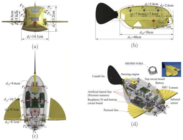
Figure 1 Dimensions and hardware configuration of the robotic fish. (a) Front view. (b) Side view. (c) Top view. (d) Isometric view
The electrical system which consists of rechargeable batteries, steering engines, circuit boards, and sensors is wrapped in the sealed shell. Figure 2 shows the structure of the electrical system. Sensing unit can acquire a variety of sensor data and then send the data to the processor through IIC transport protocol. The processor does a comprehensive analysis about the surrounding environment and the movement state of the robotic fish according to the sensor data. After processing the sensor data, the processor will send motion commands to control unit. Control unit receives motion commands from the processor and then controls the steering engines connected with the paired pectoral fins and the caudal fin for producing propulsive forces .
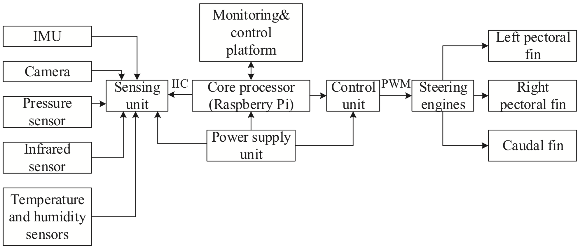
Figure 2 The electrical system of the robotic fish
Specifically, a central pattern generator (CPG) based controller is designed to control the locomotion of the robotic fish. Through controlling the steering engines with given CPG parameters, the fins are able to oscillate with given frequencies, amplitudes and offsets. Using the propulsive forces generated by the fins, the robotic fish is able to realize multiple three-dimensional swimming patterns which specifically include forward/backward swimming, left/right turning, upward/downward swimming, and clockwise/counter-clockwise yawing/pitching/rolling, as shown in Figure 3.
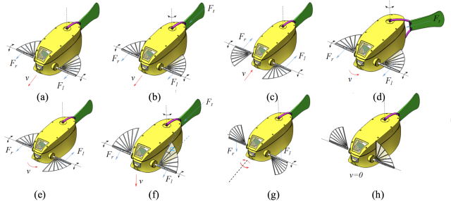
Figure 3 Several typical swimming modes of the robotic fish. (a) Forward swimming [MPF mode]. (b) Forward swimming [BCF+MPF mode]. (c) Backward swimming. (d) Turning on the movement. (e) Turning action with MPF mode. (f) Up-down locomotion. (g) Rolling. (h) Braking
The sensors include an inertial measurement unit (IMU), a camera, an infrared sensor and nine pressure sensors. IMU, camera and infrared sensor are all placed at the central area in the front of the robot. IMU provides the acceleration and attitude information of the robotic fish so that its three-dimensional motions can be monitored. Camera and infrared sensor are used together to capture the surrounding environment. Thus, the robotic fish can avoid obstacles and locate itself. Pressure sensors are distributed over the surface of the shell to establish an ALLS, for measuring the external pressures. Besides, multiple 32-bit micro controllers (STM32F405) on the two circuit boards serve the functions of multisensory data acquisition and locomotion control. Specifically, the top circuit board serves the function of pressure data acquisition. The bottom circuit board is used for controlling steering engines and collecting data of camera, infrared sensor and IMU. In addtion, a credit card-sized micro-computer called Raspberry Pi is adopted as a main processor of the robotic fish. Based on a Linux system (Detain) installed on Raspberry Pi, the robotic fish can be operated autonomously.
In order to realize observation and control of the robotic fish, we have designed a monitoring and control platform as shown in Figure 4. The platform can be used for parameters displaying, parameters adjustment, and motion control of the robotic fish. It is mainly composed of five major parts which are showed in Figure 4. Area I represents underwater image-displaying area. Area II represents sensor data-displaying area. Area III represents network-setting area. Area IV represents motion-control area.
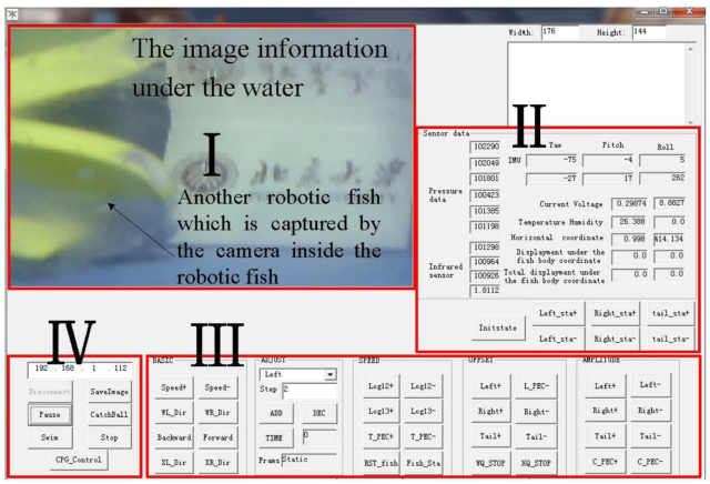
Figure 4 The monitoring and control platform of the robotic fish
Underwater image-displaying area: Camera equipped with the robotic fish is used to collect the image information under the water. And the information can be transmitted to the upper monitoring and control platform through Wi-Fi, so that the image will be displayed in image-displaying area.
Sensor data-displaying area: This area is mainly used to display the data collected by the sensors installed in the robotic fish. These sensors include infrared sensor, pressure sensors, and IMU.
Network-setting area: This area is mainly used to set the IP address of the upper platform which must match with the IP address of the robotic fish. Only in this way can data communication be carried out between the platform and the robotic fish. There are also some buttons being used to control the motion of the robotic fish.
Motion-control area: The buttons in this area are used to control the frequency, offset, and amplitude of the fins.
Using the boxfish-like robot, our group has conducted researches on lateral line inspired sensing, bio-inspired electrocommunication, underwater robot localization, autonomous swimming gait optimization, etc., as shown in Figure 5-8. More corresponding information can be found in [1]-[5].
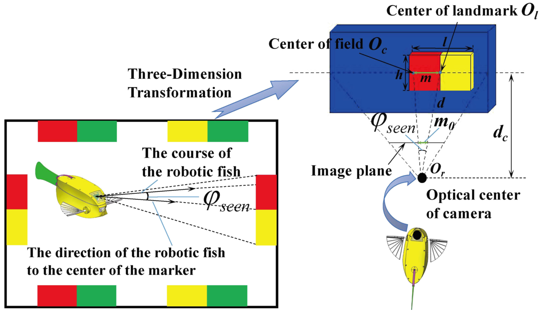
Figure 5 Schematic diagram of underwater localization research
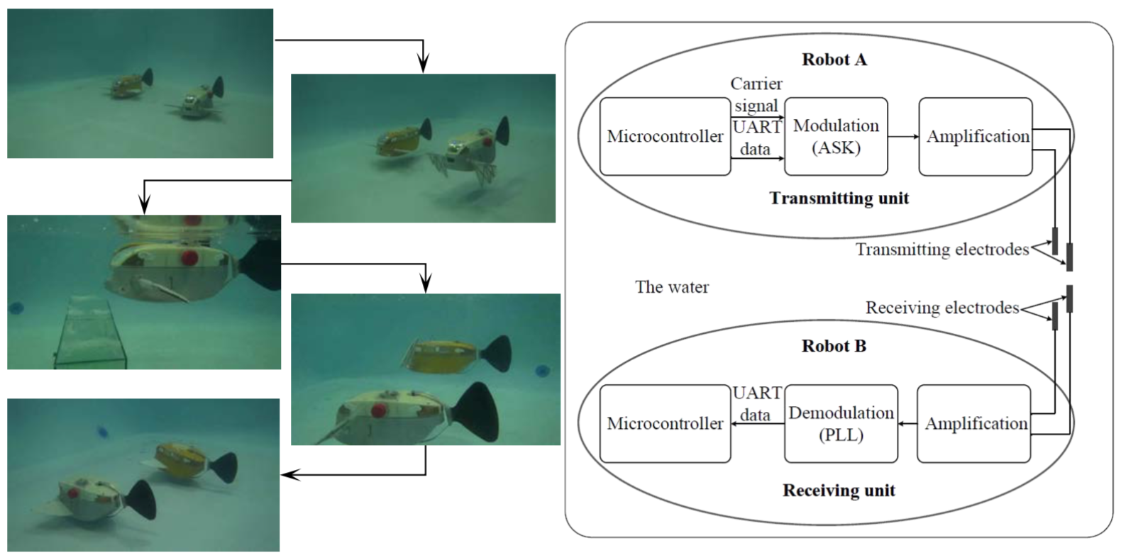
Figure 6 Schematic diagram of underwater electrocommunication research
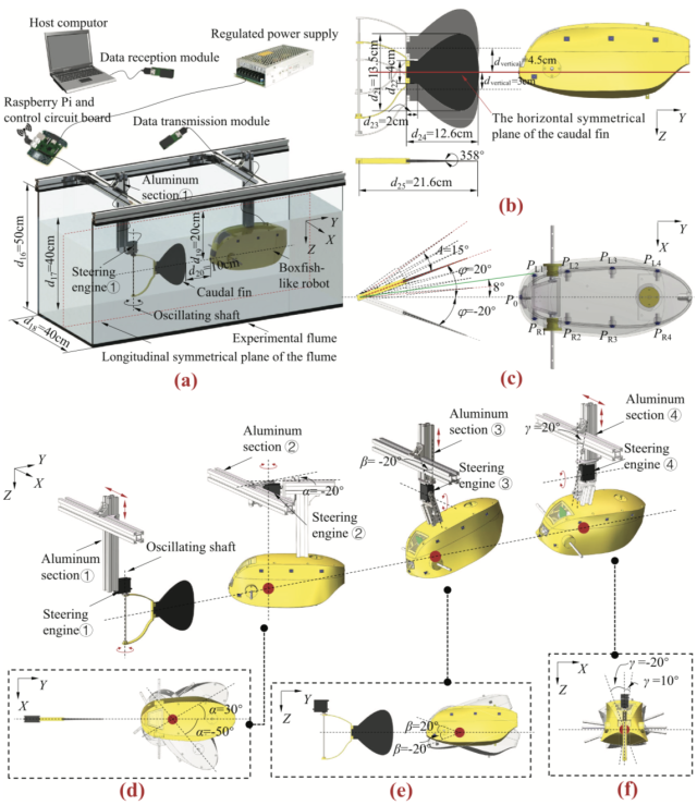
Figure 7 Schematic diagram of lateral inspired sensing research
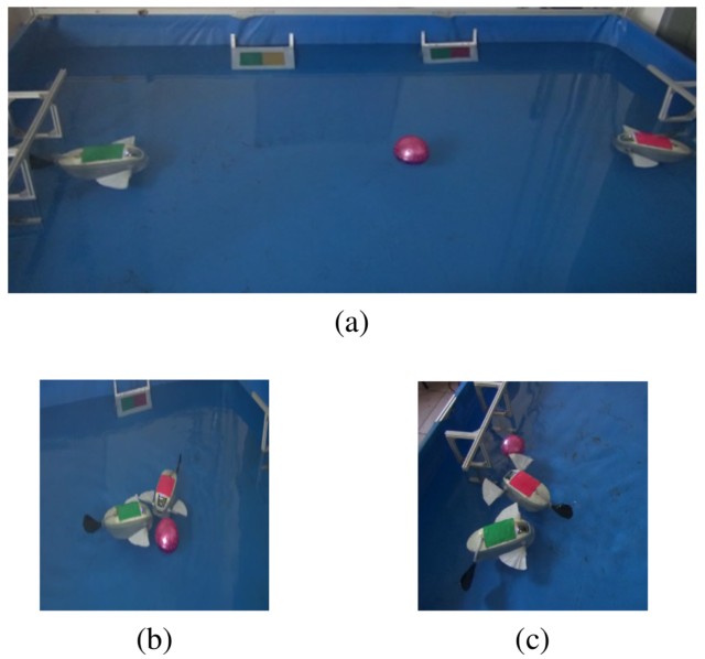
Figure 8 Schematic diagram of the vision-based autonomous robotic fish competition. (a) Beginning of the water polo game. (b) Scrimmaging. (c) Goal
Reference
[1] Xingwen Zheng, Chen Wang, Ruifeng Fan, and Guangming Xie* , “Artificial lateral line based local sensing between two adjacent robotic fish”, Bioinspiration & Biomimetics, 13, 016002, 2018.
[2] Wei Wang, Jindong Liu, Guangming Xie*, Li Wen, and Jianwei Zhang, “A Bio-inspired Electrocommunication System for Small Underwater Robots”, Bioinspiration & Biomimetics, 12, 036002, 2017.
[3] Wei Wang, Dongbin Gu, and Guangming Xie*, “Autonomous Optimization of Swimming Gait in a Fish Robot with Multiple Onboard Sensors”, IEEE Transactions on Systems, Man and Cybernetics: Systems, 2017.
[4] Wei Wang, and Guangming Xie*, “Online High-Precision Probabilistic Localization of Robotic Fish Using Visual and Inertial Cues”, IEEE Transactions on Industrial Electronics. 62(2), pp. 1113-1124, 2015.
[5] Wei Wang, and Guangming Xie*, “CPG-based Locomotion Controller Design for a Boxfish-like Robot”, International Journal of Advanced Robotic Systems. 11(87), pp. 2014.